|
Magnetic Signal Company Maintenance Manual
MAINTENANCE OF THE MAGNETIC WIGWAG
In the following account refer to Magnetic Signal Company's Bulletin No. 54 and the accompanying illustrations.
To obtain the most reliable operation of the wigwag the following
features of maintenance and adjustment must be observed.
1. The mechanism is to be maintained in an approximately level position.
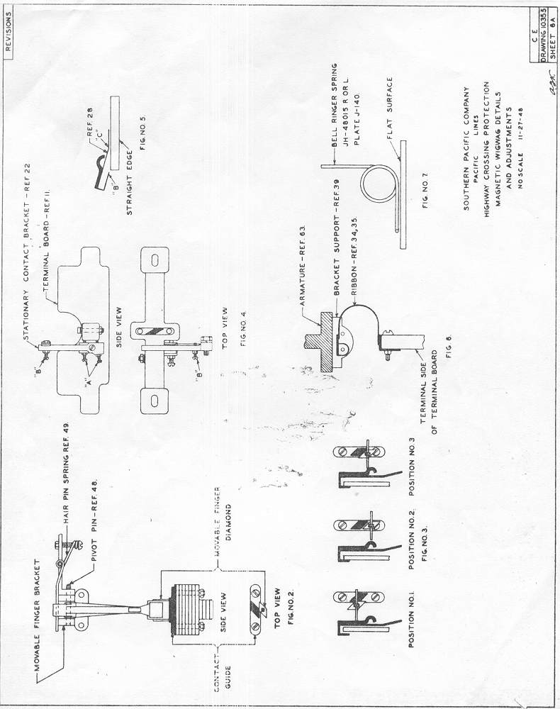
2. Movable Finger Contact - Ref. 45, P1 J112
The movable finger contact is to fit its pivot pin (Ref. 48)
closely so that very little lost motion in a plane parallel to the
pivot pin is obtained. Not more than 1/16" measured at the lower
end of the finger. Excessive play can be corrected only by
replacement of worn parts.
When replacing movable finger, pivot pin or bracket be sure that pivot
pin is clean and polished and that movable finger swings freely with no
tendency to bind. Also, be sure that movable finger ribbon is
attached as shown in plate Jl12 and that cotter pin is properly
spread. I Do not bend or otherwise change shape of new movable
finger.
The tension of each leg of the hairpin spring (Ref. 49) shall be
equal against the top of the movable finger and when movable finger is
in the central position each leg is to rest simultaneously on top of
the movable finger and the top of the bracket (Ref. 44a).
If properly adjusted, the movable finger will definitely return to a
central position after movement in either direction.
The position of the movable finger is adjustable by means of oversize
holes in the bracket (Ref. 44a) where it is attached to bracket
support ('Ref. 39). When adjusting be sure that banner is
hanging tin a perfectly vertical position, not influenced by wind, then
locate movable finger diamond so that it rests centrally in relation to
the diamond contact guide (Ref. 18) as shown in Fig.
2. Recheck the adjustment after the mounting screws are
tightened.
Replace movable finger if its diamond becomes badly worn or chipped or
if the contact wings are worn to less than one-half their original
length.
Lubricate the diamonds with a small amount of light grease such as
Alemite. Carefully remove old grease each time this operation is
performed. Lubricate the pivot pin with Pale Semaphore Oil.
3. Terminal Board - Ref. 11, Pl. Jl12.
The terminal board is adjustable laterally by means of slotted holes
where it is attached to base casting and it is to be so located that
the center of the stationary contact guide (Ref. 18) is in direct
line with the center of the movable finger diamond when in its free
position, after leaving the movable finger stop (Ref. 15) and as
it first engages contact guide (Ref. 18) in its downward stroke
When adjustment is completed, tighten the mounting screws. Where
porcelain terminal boards are used, care must be taken not to
overtighten the screws to avoid breakage. Where Bakelite terminal
boards are used, these screws may be tightened firmly.
4. Movable Finger Stop - Ref. 15, Pl. Jl12.
The function of the movable finger stop is to guide the path of the
movable finger diamond. It is to extend outward at right angles
to the length of the terminal board and parallel vertically to the path
of the movable diamond. Do not bend this part unless necessary to
correct an already distorted adjustment. The stop is adjustable
by means of slotted holes where it is attached to the terminal board
and it is to be set to provide tension of 1/32" against the side of the
movable diamond. This holds the movable diamond 1/32" out of
alignment with the stationary diamond. Do not make this
adjustment until the movable finger and the terminal board have been
properly adjusted.
5. Stationary Contact Adjustment.
New Stationary Contacts (Ref. 28) are usually properly bent to
provide proper contact pressure when received and require no
alteration; however, each contact should be checked as shown in
Fig. 5 before it is installed. With the slotted end or the
contact held against a flat surface the point "B" of the contact should
be in the same plane. Should any bending be necessary to obtain
this adjustment, it must be confined to point “C”. The end "B" is
to be parallel to the contact. No other bending or this part is
permitted.
The top member of the Stationary Contact Bracket is to extend across
the top of the terminal board at "right angle" and no bending or this
part is permitted other than to correct already faulty adjustment.
When the stationary contact is assembled on its bracket, the screws
shown as "A" in Fig. 4 are to be adjusted so that when the
mechanism is in its normally inoperating position and the contacts are
engaged, the top member of the contact bracket is located as shown in
Fig. 3 Position #1 midway between the contact finger and its
backstop and slightly closer to the contact side or the finger.
When properly adjusted, it will be found that when the mechanism is
held in a position in which the movable diamond is engaged with neither
the stationary diamond nor the movable finger stop there will be a
clearance of 1/32" to 1/16” between the contact surface of the movable
finger and the hump on the stationary contact as shown in Fig. 3
Position #2.
The Stationary Contact is adjustable laterally by means of the slotted
end where it is attached to the bracket and it is to be so adjusted
that in its downward stroke the contact surface of the movable finger
engages about 1/8" past the center of the hump on the stationary
contact as shown in Fig. 3 Position #3.
The adjusting screws shown as "A” in Fig. 4 may be used to take up the wear on the contact surfaces
of the movable finger and are to be readjusted as this wear progresses.
On mechanisms not equipped with these screws, it I will be necessary to
replace the movable finger before wear has progressed far enough to
cause loss of contact pressure.
The screw shown as "B" in Fig. 4 is to be set so that it just
touches the contact without pressure when the contacts are not engaged.
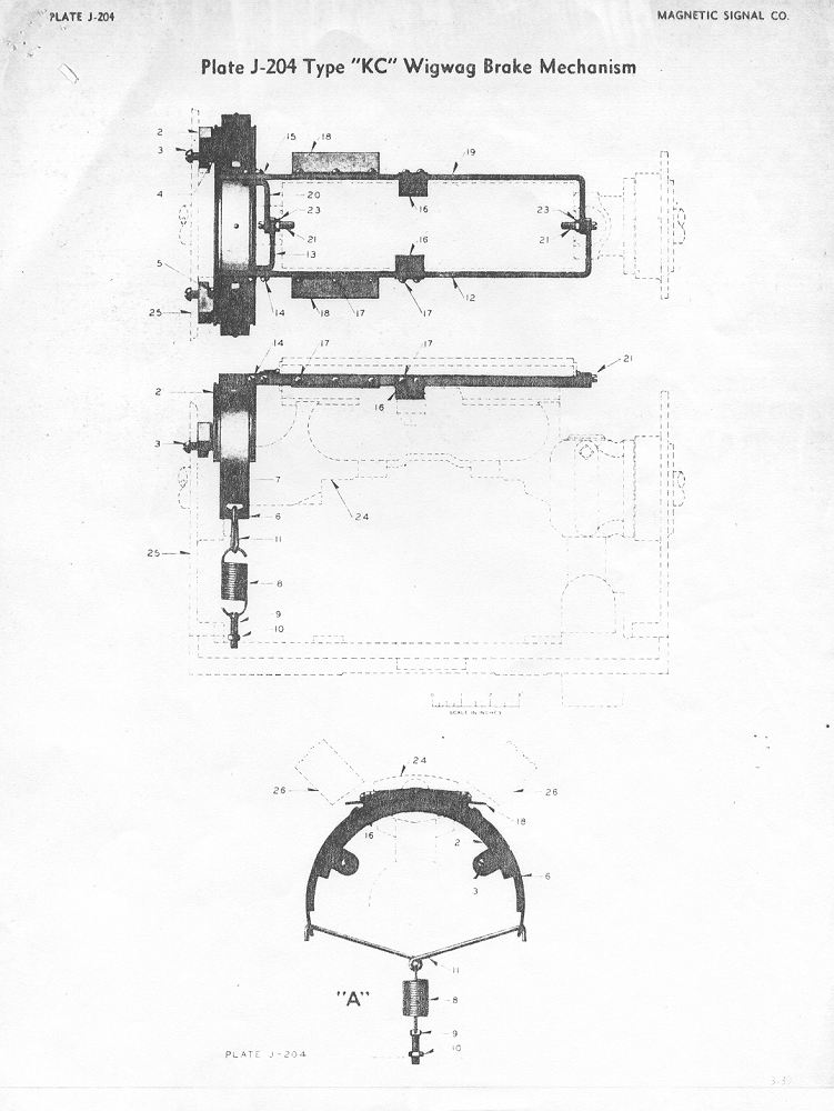
6. Brake Adjustment.
Brake mechanism is to be assembled as shown on plate J204.
The extensions of the brake arms (Ref. 19) which engage with lugs on the brake band are to clear
the top of the band 1/32" when the brake arms are in the release position and are to clear the top
of the lugs a minimum of 1/32" when the arms are picked up.
Brake arms and angle piece (Ref. 18) are to clear pole pieces a minimum of 1/8" when in the picked
up position and armature is in any part of its operating stroke.
When installing new brake arms it will probably be necessary to bend
the angle piece. (Ref. 18) to obtain proper
clearance. To avoid distortion of other parts, do not attempt to
bend the angle piece while assembled to mechanism. Remove brake
arm and hold in vice. Increasing the clearance of the angle piece
will increase the brake pickup voltage so avoid over bending. The
maximum pick up is 300 volts measured across the coils when the voltage
is gradually increased with a variable resistance in series with the
bell control.
The operating stroke of the brake arm is adjustable within certain
limits by bending the brake arm support (Ref. 16). When
this adjustment is complete, the brake arm support must be parallel to
the top of the slot in the armature when the brake is picked up.
It is frequently found that sufficient adjustment cannot be made by bending the brake arm support.
This is usually due to improperly located brake drum (Ref.
2). To set the brake drum, loosen the supporting screws
(Ref. 3) and move drum to desired position. If properly set
the ends of the brake arms will have the required clearances and will
be approximately the same distance away from the brake band in any part
or the mechanism stroke. In some instances, it may be necessary
to enlarge the holes for the supporting screws and this may be done
with a round file or 2l/64 drill.
Brake drums on mechanisms that have been shopped since March, 1941 will
have the brake drums doweled in the proper position and these are not
to be moved.
On mechanisms equip~ed with single brake spring shown as Ref. 8 in “A" plate J204, the tension of
the spring is to be adjusted so that when the wigwag is operating at
normal voltage and the operating circuit then opened, the movable
finger diamond will be heard to snap past the end of the stationary
diamond not less than three or more than four times. Spring
tension is adjustable by means of screw (Ref. 9) which attaches
spring to base casting.
On mechanisms equipped with double springs as shown in Fig. 1 the
same braking action as described for the single spring is
required. To adjust first turn both spring supporting screws
upward until springs are slack, then hold the brake band so that it is
centered in relation to the armature and turn each screw downward until
the turns in the spring just start to separate. If further
adjustment is necessary, turn each screw equally.
1. Ribbons are to be installed as shown in Fig. 6, with the
loop and connections pointing toward the outside door. Replace
ribbons if breakage of the fine strands has started to develop.
Ribbons are to be somewhat shortened from their full extended length by
uniformly bunching the weave together, are to be carefully trained in a
position that prevents contact with other parts.
8. Bell Mechanism - See plate JH 140.
Internal operating parts of the bell mechanism shall be inspected every three months or whenever
faulty action of the gong indicates that attention is required.
Remove bell cover casting with gong attached to make this
inspection. Check wearing surfaces of striker hub pawls JH48221
and stationary bell tripper JH48222 and replace if badly worn.
Remove gummed oil and dirt and apply Pale Semaphore Oil on the pivot
pins and a small amount of light grease at the point where the tripper
engages the pawls.
Replace rubber buffers JH48053 if worn or grooved from contact with the
striker hub or if distance between the ends of the bell tripper and
striker hub pawl is less than 1/8't. When installing new
buffers adjust their length to provide a clearance 3/16” between the ends of the bell tripper and striker hub pawls.
Bearing surfaces of striker hubs, JH48208R and L, are to be kept free of gummed oil and dirt and
lubricated with Pale Semaphore oil. Disassemble for cleaning if
necessary. Bell ringer springs, JH8015R and L, are to be replaced
if broken or badly distorted from their original shape. A
properly adjusted spring will appear as shown in Fig. 7.
With the bottom leg of the spring, which engages with the striker hub,
held against a flat surface, the leg of the spring which engages the
spring stop should be at approximately “right angle” to the flat
surface.
Bell strikers JH48016 should strike the gong with equal force to obtain uniform sound. Strikers are
adjustable by means of cap screw JH48028 and they are to be set so that
the mechanism, in the vertical inoperating position, gives a clearance
of approximately 1/8" between the striking edge of each striker and the
gong shell. Tighten cap screws when adjustment is complete.
Assembly of the gong shell JH4812 to bell cover must be kept tight to provide a clear audible tone of the gong.
9. Gaskets on doors (Ret. 103, Plats J1l2) are to be kept
in good condition to keep out dust and insects. It gaskets are
defective, replace the door and send to shop for repairs.
10. Flag holder casting (Ref. 94. Plate Jl12) is to
be kept tight on the armature shaft. Erratic action or failure of
the wigwag will result from improper location of this part.
Should considerable play be found at this point, it is probable the
taper key is worn and the mechanism should be shopped.
11. Banner pipe is to be kept securely tightened in the flag
holder casting. Banners are to be kept neatly painted and
roundels clean. Inspect lamp receptacle, wiring and
connections. Should a banner be found which has been damaged in
any way, such as being struck by a high load on a truck, replace the
banner and carefully inspect all other details of the mechanism.
A broken armature shaft may not immediately interfere with the wigwag
operation but can result in ultimate failure if not detected.
12. Ball bearings (Ref. 68 and 69) are to be oiled every
three months with Pale Semaphore Oil. Our mechanisms are equipped
with several types of bearings which are shielded in various manners
and
as the shields may prevent the oil from reaching the bearings, an
effort must be made to apply oil, to both sides. The oil cup
where provided is intended for the outside and the grooves in the
armature hub next to the end castings are for the inside. If “(half shielded bearings - oil inner
side only)” has been marked on the magnet assembly, the oil need be applied to the inner side only.
Do not get oil on wiring or other parts where oil is not
intended. Carefully wipe up surplus oil which drains from the
bearings.
13. The air gap between the armature and magnet pole pieces is
set to a minimum of . 010" in the shop. This clearance is
sometimes impaired by rust growth on the pole surfaces, warpage of the
castings or bearing wear. Check this clearance occasionally with
a feeler guage and if a clearance of less than . 007" is
found. when the coils on the side being tested are energized at
their normal operating voltage change out the mechanism.
14. When new wigwag is installed and at least once yearly
thereafter, it must be tested to see that it will operate reliably on
its minimum rated operating voltage which is 5. 5 volts. To
make this test, connect a variable resistance having a capacity of at
least 4 amperes in series with the control wire. With the control
wire energized and the banner held stationary in the vertical position,
adjust the resistance so that 5. 5 volts is obtained across the
magnet coils. Then open the control circuit, let the banner come
to rest and again close the control circuit. The wigwag must
start in both directions and operate reliably with this amount of
resistance in the circuit. If wigwag fails to meet this test
check all features outlined herein and if this fails to correct the
conditions, change it out.
15. Should wigwags be encountered in which adjustments as outlined herein are not obtainable,
change them out and send to shop for correction. "
FEATURES TO BE OBSERVED IN THE SHOP
1. Porcelain terminal boards are to be replaced with bakelite terminal boards. (Ref. 11, Plate J1l2)
2. Porcelain bracket supports are to be replaced with bakelite bracket support (Ref. 39, Plate Jl12)
3. Stationary contact brackets which are not equipped with
adjusting screws, shown as "A” in Fig. 4, shall be so
equipped. Use a factory equipped bracket to obtain detail for
this work. It will probably be necessary to file the side of the
bracket adjacent to the projection on the side of the terminal board to
obtain approximately 1/16" clearance.
4. When ordering new condensers to replace contact condenser (Ref. 107, Plate J1l2) specify G. E.
Pyranol Capacitors No. 23F381G10l, 2000 Volts DC Capy.
1. 0 M. F. D. Two of these will be required to
replace the one double unit (Ref. 107). The new capacitors
are to be located near the banner end of the base casting on the
terminal side of the terminal board in such position that they do not
interfere with brake adjustments or with terminals. They are to
be attached by 3/8" X 10-32 round head screws and lock washers tapped
into the base casting.
5. Mechanism is to be wired for independent lamp control as shown
on wiring diagram JH52l, Plate 10 Bulletin No. 54 unless other
special arrangements are specified.
6. No welding is to be done on wigwag parts other than top cover
casting (Ref. 90, Plate Jll2) or bell cover casting (Ref.
75).
7. Mechanism is to be completely dismantled and all parts
thoroughly cleaned. All cast iron parts are to be painted with
aluminum paint, care being taken to keep paint off pole surfaces of
armature and magnets. These are to be treated with Union Pole
Face Treatment or a good grade of clear lacquer when other adjustments
are completed. Also keep paint from all other assembly surfaces.
8. If insulation on field coils and leads are in good condition,
coils are not shorted or loose on pole pieces, they need not be removed
from the pole pieces. Replacement coils are 1. 3 ohms each
and consist of 400 turns of No. 15 enameled magnet wire.
Coils may be either shop made or purchased.
On mechanisms not already equipped with coil supports (Ref.
81. Plate Jl12) one of these is to be installed on each side of
each coil in the center of the pole piece. Coils are to be firmly
wedged in place with maple wedge (Ref. 86).
Magnet coils are to be so connected that the same relative magnet
polarity is obtained on each side. This may be tested by use of a
compass. When the coils are energized, the pole pieces nearest
the gong end of the mechanism shall attract the same end of the compass
needle and the pole pieces nearest the gong end shall attract the
opposite end of the needle.
9. Ball Bearings.
Unshielded type ball bearings are to be discarded. Bearings are
to be shielded on one side only and installed on the armature with the
shied toward the outside of the mechanism. One shield may be
removed from a fully shielded bearing. On mechanisms so equipped
remove the oil cup (if any) and I plug the hole. Print plainly
across the magnet assembly on both sides "Half shielded bearings -
oil inner side only".
Bearings that are to be reused must be carefully cleaned and freed from
all traces of hardened grease. If cleaned bearing does not spin
freely without roughness do not reuse. Bearings are to be packed
with light Marfax grease to protect them while mechanism is in
storage. This will be supplemented by periodical lubrication with
Pale Semaphore Oil in the field.
10. Brake Drum - (See Plate J204, Bulletin No. 54).
Brake drum (Ref. 2) is to be accurately located on the end
casting with its outside circumference on a 3-1/2" radius to the center
of the armature shaft. Shops repairing these mechanisms are
equipped with a special tool for this purpose. After drum is
tightened in the proper position, it is to be secured by dowels (#1
taper pins) installed through end casting and drum adjacent to the
mounting screws. This may be done before mechanism is
reassembled. Brake arms (Ref. 19 and 12) are to be adjusted
as described in part 6 of the Maintenance Section. If difficulty
is experienced in obtaining adjustment check the location of the
armature pins (Ref. 21) and the slot in the side of the armature
which engages the brake arm support. (Ref. 16). The
pin should be located in the center of the armature with the center of
the pin 5/8" below the top of the armature. The top of the slot
should be 15/16" below the top of the armature.
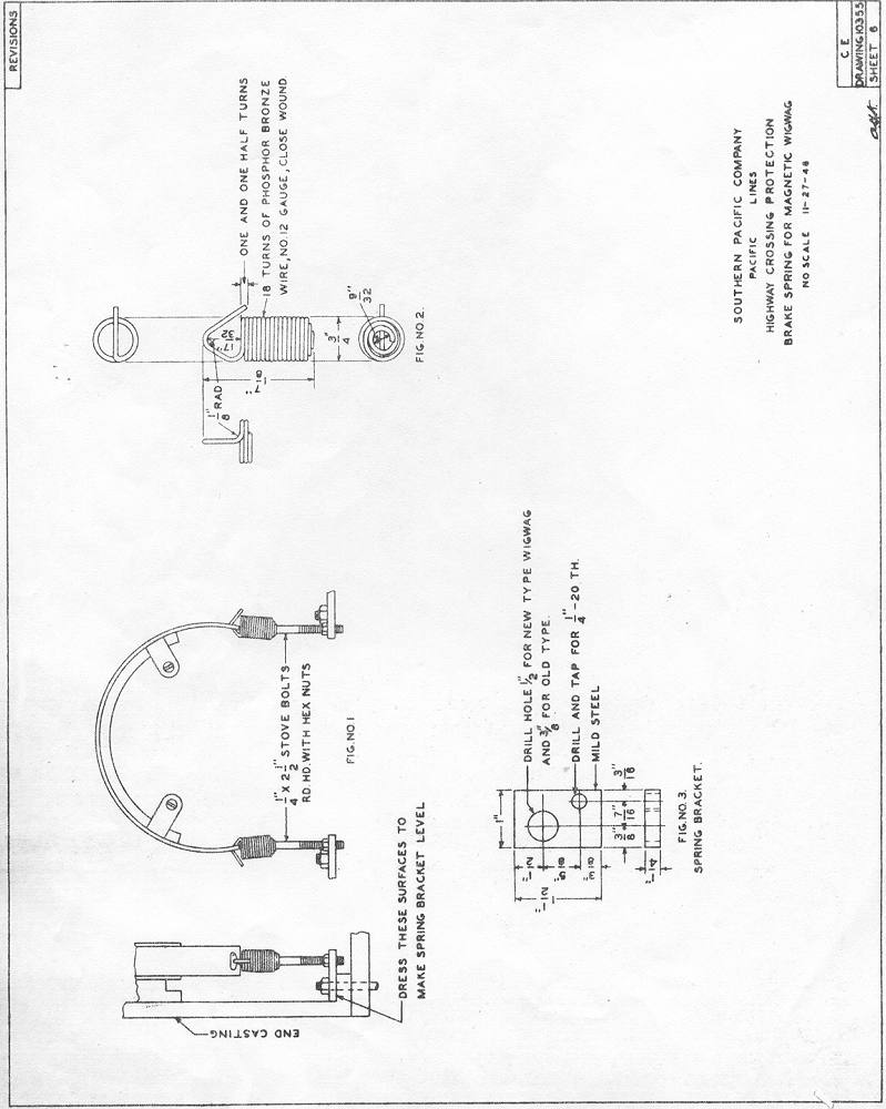
Brake Springs - (See Brake Spring Plan).
Brake springs are to be installed as shown on the brake spring plan.
Spring (Fig. 2) is secured to spring bracket (Fig. 3) by
means of 1/4" X 2-1/2" stove bolts, the smooth section of the stove
bolt providing free escapement for the downward motion or the spring.
Spring bracket (Fig. 3) is secured by the existing machine bolts
which attach the end casting to the base casting. In some
instances, it may be necessary to use longer machine bolts to provide a
full length thread for the nut. The top portion of the base on
the end casting is usually slightly sloped or may have rough
projections which will prevent the spring bracket from extending
straight out from the end casting. In these instances, it will be
necessary to dress the bottom of the spring bracket with a file or
to chip rough projections from the castings. The spring bracket
must be parallel to the base casting and stove bolt must extend
straight up and parallel to the end casting.
Adjustments after assembly shown in Fig. 1 are made as described in 6 in the Maintenance Section.
11. The following procedure is to be observed when assembling wigwag mechanism:
a First assemble end castings, bearings and armature to base casting
with bearings in perfect alignment. Do not force or spring end
castings into position to obtain alignment of holes for dowel pin
(Ref. 61). In some mechanisms, the existing dowel holes may
not provide perfect alignment of bearings and it may be necessary to
re-ream them and install oversize pin or to drill new dowel holes after
the end castings have been tightened to the base casting. The
armature must move with perfect freedom. Plug unused dowel holes
b Install flag holder casting as follows: Invert the mechanism on the
testing table in an approximately vertical position and secure it in
this position so that it will not move. Attach the special
protractor, which has been provided for this purpose, to the end
casting by means of the striker hub pivot screw holes. Attach the
pointer to the armature shaft and set it to read zero on the protractor
scale. Move the armature by hand and allow it to return gradually
to zero by gravity. If bearings are perfectly free, a
zero reading will be obtained after movement in either direction.
Install the flag holder casting and tighten screws just tight enough
that casting can be twisted on the shaft. Install taper pin
(Ref. 96) and drive it just tight enough to bring the holes into
alignment. Install the "Test Banner" which has previously been
perfectly balanced. If the flag holder casting is properly
located, the pointer on the protractor will read zero and the flag
holder casting screws can be tightened securely and taper pin driven
firmly. If the reading obtained is not zero, remove the taper
pin, locate the casting as required and tighten screws (Ref.
59). If the difference in the alignment of the taper pin holes is
not too great, ream with taper pin reamer and install oversize
pin. If the banner is perfectly balanced, a zero reading will
also be obtained if the banner is rotated one-half turn in the flag
holder casting. Remove banner when above adjustments are
complete.
c Set mechanism right side up and fasten to test table in level
position. Install banner and re- set protractor pointer to
zero. Then install magnets. The back portion of the pole
pieces of part (Ref. 28) are machined for approximately one-half
their surface on a 4-3/8” radius conforming with radius of swinging
armature (Ref. 63). The remaining one-half portion of the
pole surfaces are machined on a straight angle to provide additional
clearance on the initial pullover of the armature. The initial
setting of the magnets should be made so that the radius of the back
portion of the pole pieces is parallel to the radius of the armature,
although in final adjustment it may be necessary to tilt the magnets
slightly toward the armature which will decrease the front clearance
and increase the pullover from the normal vertical position of the
armature. Generally, the front edge of each pole piece is located
from 1/4" to 5/16" from the edge of the armature when in its normal
vertical position although the magnets should be actually set by
determining the position that will provide the greatest magnetic pull
at minimum voltage upon breaking of the movable finger contact.
This occurs at 11 degrees from the vertical position in either
direction. When the magnets are finally adjusted tho mechanism
must start and move
a minimum of 11 degrees in either direction when a maximum of 4. 8 volts is applied to the coils.
This test is made with a voltmeter connected across the coils and a
variable resistor in series with the coils. Adjust voltage while
banner is held stationary, open the circuit and reclose when the banner
is at rest.
The minimum air gap between the armature and pole faces is to be not
less than . 0l0" after the finish has been applied and when the
coils are energized at 8 volts.
After the magnet adjustments are complete they are to be locked in
position by pouring molten lead in the space where mounted on the end
castings.
d Install movable finger contact, terminal board and stationary
contacts and adjust as outlined in maintenance sections 2,3,4,5 and 7.
e Install bell ringer parts and adjust as outlined in maintenance Section 8.
f Install brake parts and adjust as before described.
g On final test the wigwag must start in either direction and operate
full stroke on a maximum of 5. 5 volts. Test as described
in "C”.
Brake pick up measured on a gradual increase of voltage should not exceed 3. 0 volts.
h Complete assembly, top casting, etc. and securely tie armature to prevent movement in shipment.
February 12, 1949
Plate J-112
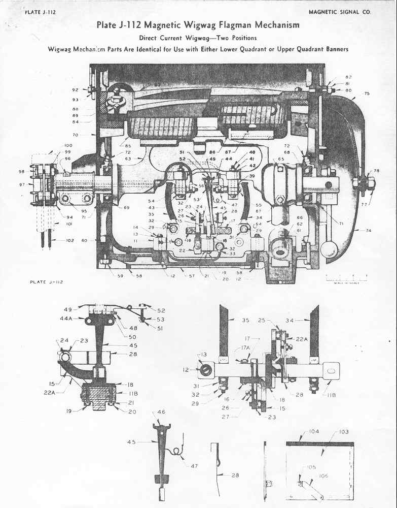
Plate J-140
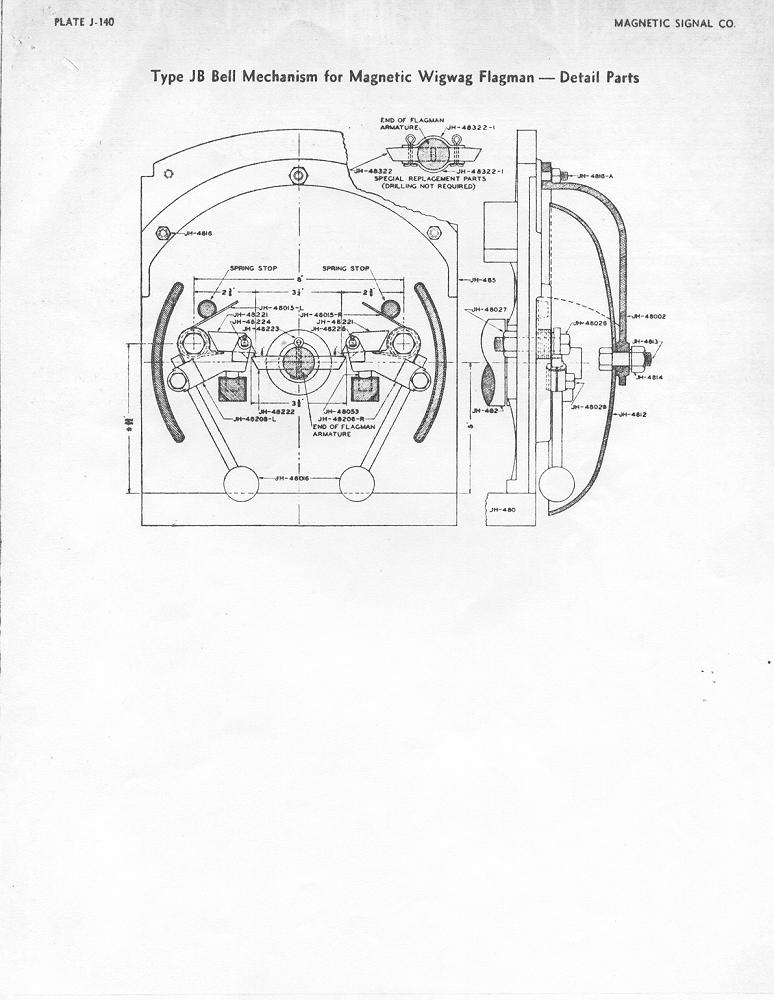
Plate J-204
Revision Sheet 6
Revision Sheet 6A
|
|
|